E700 Drivers
The E700 Series is the latest generation of Mitsubishi Electric’s Micro Sized Variable Frequency Drives. It replaces the popular E500 Series and utilizes the same mounting foot print. Advanced features and functions such as USB port for commissioning and monitoring, embedded M-dial and display, increased low speed performance and the ability to install one of the many 700 Series option cards allows the E700 to be used in the most demanding applications. With a standard 5 year warranty, quality and reliability is essentially guaranteed. The E700 Series promises to continue Mitsubishi’s long history of providing the best micro drive in the industry.
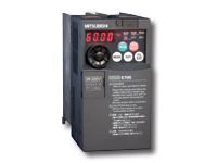
E700 Series The cost-effective variable speed control solution for general purpose applications.
- Available in 115V, 240V and 480V up to 20HP
- Advanced Magnetic Flux Vector Control for improved starting torque and smooth low speed motor operation
- Auto-tuning allows improved performance using virtually any manufacturer’s motor
- All capacities include built-in brake chopper
- USB communications allow fast commissioning and troubleshooting
- Standard RS485 serial communications supporting Modbus® RTU
- Sink / Source selectable I/O
- Supports remote I/O function via network
- Built-in PID Control
- Delivers rated current at 50°C and 14.5kHz carrier frequency with minimal de-rating
- 200% overload for 3 seconds
- 0 to 10V analog output
- CC-Link®, DeviceNet™, Profibus-DP, LonWorks®
- Standard 5 year warranty

HP |
Output Amps |
Model Number |
Dimensions in inches (mm) |
Weight Lbs (kg) |
Stocked Item |
|
|
|
Height |
Width |
Depth |
|
|
1-Phase 100~120VAC Input / 3-Phase 200~240VAC Output |
1/8 |
0.8 |
FR-E710W-008-NA |
5.0 (128) |
2.7 (68) |
3.2 (80.5) |
1.1 (0.5) |
S |
1/4 |
1.5 |
FR-E710W-015-NA |
5.0 (128) |
2.7 (68) |
4.4 (110.5) |
1.3 (0.6) |
S |
1/2 |
3 |
FR-E710W-030-NA |
5.0 (128) |
2.7 (68) |
4.5 (112.5) |
2.0 (0.9) |
S |
1 |
5 |
FR-E710W-050-NA |
5.0 (128) |
6.7 (170) |
6.1 (155) |
7.5 (3.4) |
S |
1-Phase 200~240VAC Input / 3-Phase 200~240VAC Output |
1/8 |
0.8 |
FR-E720S-008-NA |
5.0 (128) |
2.7 (68) |
3.2 (80.5) |
1.1 (0.5) |
S |
1/4 |
1.5 |
FR-E720S-015-NA |
5.0 (128) |
2.7 (68) |
3.2 (80.5) |
1.1 (0.5) |
S |
1/2 |
3 |
FR-E720S-030-NA |
5.0 (128) |
2.7 (68) |
6.2 (157.6) |
1.3 (0.6) |
S |
1 |
5 |
FR-E720S-050-NA |
5.0 (128) |
4.3 (108) |
5.4 (135.5) |
3.1 (1.4) |
S |
2 |
8 |
FR-E720S-080-NA |
5.0 (128) |
4.3 (108) |
6.4 (161) |
3.1 (1.4) |
S |
3 |
11 |
FR-E720S-110-NA |
5.9 (150) |
5.5 (140) |
6.2 (155.5) |
4.2 (1.9) |
S |
3-Phase 200~240VAC Input & Output |
1/8 |
0.8 |
FR-E720-008-NA |
5.0 (128) |
2.7 (68) |
3.2 (81) |
1.1 (0.5) |
S |
1/4 |
1.5 |
FR-E720-015-NA |
S |
1/2 |
3 |
FR-E720-030-NA |
5.0 (128) |
2.7 (68) |
4.5 (113) |
1.6 (0.7) |
S |
1 |
5 |
FR-E720-050-NA |
5.0 (128) |
2.7 (68) |
5.3 (133) |
2.2 (1.0) |
S |
2 |
8 |
FR-E720-080-NA |
5.0 (128) |
4.3 (108) |
5.4 (136) |
3.1 (1.4) |
S |
3 |
11 |
FR-E720-110-NA |
S |
5 |
17.5 |
FR-E720-175-NA |
5.0 (128) |
6.7 (170) |
5.7 (143) |
3.8 (1.7) |
S |
7 1/2 |
24 |
FR-E720-240-NA |
10.3 (260) |
7.1 (180) |
6.5 (165) |
9.5 (4.3) |
S |
10 |
33 |
FR-E720-330-NA |
S |
15 |
47 |
FR-E720-470-NA |
10.3 (260) |
8.7 (220) |
7.5 (190) |
19.9 (9) |
S |
20 |
60 |
FR-E720-600-NA |
S |
3-Phase 380~480VAC Input & Output |
1/2 |
1.6 |
FR-E740-016-NA |
5.9 (150) |
5.5 (140) |
4.5 (114) |
3.1 (1.4) |
S |
1 |
2.6 |
FR-E740-026-NA |
S |
2 |
4 |
FR-E740-040-NA |
5.9 (150) |
5.5 (140) |
5.4 (135) |
4.2 (1.9) |
S |
3 |
6 |
FR-E740-060-NA |
S |
5 |
9.5 |
FR-E740-095-NA |
S |
7 1/2 |
12 |
FR-E740-120-NA |
5.9 (150) |
8.7 (220) |
5.8 (147) |
7.1 (3.2) |
S |
10 |
17 |
FR-E740-170-NA |
S |
15 |
23 |
FR-E740-230-NA |
10.3 (260) |
8.7 (220) |
7.5 (190) |
19.9 (9) |
S |
20 |
30 |
FR-E740-300-NA |
S |
E700 General Specifications
Control Specifications |
Control Method |
Soft-PWM control/high carrier frequency PWM control (V/F control, advanced magnetic flux vector control, general-purpose magnetic flux vector control, optimum excitation control can be selected) |
Output Frequency Range |
0.2 to 400Hz |
Frequency Setting Resolution |
Analog Input |
0.06Hz/60Hz (terminal2, 4: 0 to 10V/10bit)
0.12Hz/60Hz (terminal2, 4: 0 to 5V/9bit)
0.06Hz/60Hz (terminal4: 4 to 20mA/10bit) |
Digital Input |
0.01Hz |
Frequency Accuracy |
Analog Input |
Within ±0.5% of the max. output frequency (25°C ±10°C) |
Digital Input |
Within 0.01% of the set output frequency |
Voltage/Frequency Characteristics |
Base frequency can be set from 0 to 400Hz. Constant torque/variable torque pattern can be selected |
Starting Torque |
200% or more (at 0.5Hz) when advanced magnetic flux vector control is set (3.7K or less) |
Torque Boost |
Manual torque boost |
Acceleration/Deceleration Time Setting |
0.01 to 360s, 0.1 to 3600s (acceleration and deceleration can be set individually), linear or S-pattern acceleration/deceleration mode can be selected. |
Regenerative Braking Torque (*1) |
FR-E720-008 and 015, FR-E720S-008 and 015, FR-E710W-008 and 015 ..... 150%, FR-E720-030 and 050, FR-E740-016 and 026, FR-E720S-030 and 050, FR-E710W-030 and 050 ..... 100%, FR-E720-080, FR-E740-040, FR-E720S-080 ..... 50%, FR-E720-110 or more, FR-E740-060 or more, FR-E720S-110 ..... 20% |
DC Injection Brake |
Operation frequency (0 to 120Hz), operation time (0 to 10s), operation voltage (0 to 30%) variable |
Stall Prevention Operation Level |
Operation current level can be set (0 to 200% adjustable), whether to use the function or not can be selected |
Operation Specifications |
Frequency Setting Signal |
Analog Input |
Two points
Terminal 2: 0 to 10V, 0 to 5V can be selected; Terminal 4: 0 to 10V, 0 to 5V, 4 to 20mA can be selected |
Digital Input |
Entered from operation panel and parameter unit |
Start Signal |
Forward and reverse rotation or start signal automatic self-holding input (3-wire input) can be selected. |
Input Signal |
Seven points: You can select from among multi-speed selection, remote setting, stop-on contact selection, second function selection, terminal 4 input selection, JOG operation selection, PID control valid terminal, brake opening completion signal, external thermal input, PU-External operation switchover, V/F switchover, output stop, start self-holding selection, forward rotation, reverse rotation command, inverter reset, PU-NET operation switchover, External-NET operation switchover, command source switchover, inverter operation enable signal, and PU operation external interlock |
Operational Functions |
Maximum/minimum frequency setting, frequency jump operation, external thermal relay input selection, automatic restart after instantaneous power failure operation, forward/reverse rotation prevention, remote setting, brake sequence, second function, multi-speed operation, stop-on contact control, droop control, regeneration avoidance, slip compensation, operation mode selection, offline auto tuning function, PID control, computer link operation (RS-485) |
Output Signal |
Output Signal Points |
Open Collector Output |
Two points |
Relay Output |
One point |
Operating Status |
You can select from among inverter operation, up-to-frequency, overload alarm, output frequency detection, regenerative brake prealarm, electronic thermal relay function prealarm, inverter operation ready, output current detection, zero current detection, PID lower limit, PID upper limit, PID forward/reverse rotation output, brake opening request, fan alarm*3, heatsink overheat pre-alarm, deceleration at an instantaneous power failure, PID control activated, during retry, life alarm, current average value monitor, remote output, alarm output, fault output, fault output 3, and maintenance timer alarm |
For Meter Output Points |
Analog Output |
0 to 10VDC: one point |
For Meter |
You can select from among output frequency, motor current (steady), output voltage, frequency setting, motor torque, converter output voltage, regenerative brake duty, electronic thermal relay function load factor, output current peak value, converter output voltage peak value, reference voltage output, motor load factor, PID set point, PID measured value, output power 0 to 10VDC |
Indication |
Operation Panel Parameter Unit (FR-PU07) |
Operating Status |
You can select from among output frequency, motor current (steady), output voltage, frequency setting, cumulative energization time, actual operation time, motor torque, converter output voltage, regenerative brake duty, electronic thermal relay function load factor, output current peak value, converter output voltage peak value, motor load factor, PID set point, PID measured value, PID deviation, inverter I/O terminal monitor, I/O terminal option monitor, output power, cumulative power, motor thermal load factor, and inverter thermal load factor. |
Fault Definition |
Fault definition is displayed when the fault occurs and the past 8 fault definitions (output voltage/current/frequency/cumulative energization time right before the fault occurs) are stored |
Additional Display By The Parameter Unit (FR-PU04/FR-PU07) Only |
Operating Status |
Not used |
Fault Definition |
Output voltage/current/frequency/cumulative energization time immediately before the fault occurs |
Interactive Guidance |
Function (help) for operation guide |
Protective/Warning Function |
Overcurrent during acceleration, overcurrent during constant speed, overcurrent during deceleration, overvoltage during acceleration, overvoltage during constant speed, overvoltage during deceleration, inverter protection thermal operation, motor protection thermal operation, heatsink overheat, input phase failure (*6), output side earth (ground) fault overcurrent at start (*5), output phase failure, external thermal relay operation (*5), option fault, parameter error, internal board fault, PU disconnection, retry count excess (*5), CPU fault, brake transistor alarm, inrush resistance overheat, communication error, analog input error, USB communication error, brake sequence error 4 to 7 (*5)
Warning functions: Fan alarm (*3), overcurrent stall prevention, overvoltage stall prevention, PU stop, parameter write error, regenerative brake prealarm (*5), electronic thermal relay function prealarm, maintenance output (*5), undervoltage |
Environment |
Ambient Temperature |
-10°C to +50°C (14°F to 122°F) (non-freezing) (*4) |
Ambient Humidity |
90%RH maximum (non-condensing) |
Storage Temperature (*2) |
-20°C to +65°C (-4°F to 149°F) |
Atmosphere |
Indoors (without corrosive gas, flammable gas, oil mist, dust and dirt etc.) |
Altitude/Vibration |
Maximum 1000m (3280.80 feet) above sea level, 5.9m/s2 or less at 10 to 55Hz (directions of X, Y, Z axes) |
Notes:
- The braking torque indicated is a short-duration average torque (which varies with motor loss) when the motor alone is decelerated from 60Hz in the shortest time and is not a continuous regenerative torque. When the motor is decelerated from the frequency higher than the base frequency, the average deceleration torque will reduce.Since the inverter does not contain a brake resistor, use the optional brake resistor when regenerative energy is large. A brake unit (FR-BU2) may also be used.
- Temperatures applicable for a short time, e.g. in transit. As the FR-E720-008 to 050, FR-E740-016, 026, FR-E720S-008 to 030, FR-E710W-008 to 050 are not provided with the cooling fan, this alarm does not function.
- When using the inverters at the surrounding air temperature of 40°C (104°F) or less, the inverters can be installed closely attached (0cm clearance).
- This protective function does not function in the initial status.
- This protective function is available with the three-phase power input specification model only.
E700 Series Terminal Connection Diagram
One-phase 100V power input Three-phase 200V power input Three-phase 400V power input


|